


- Building Trust Beyond Technology – A Story of Service and Sincerity
- At CCMT 2026 – Business Is Important, but Trust Matters More
- U.S Client Places Repeat Orders for 1,000 Wire EDM Machine power feed contacts, Praising Superior Quality and Reliable Delivery
- European clients are satisfied with our customized End Milling Tools
- How to select grinders between Vertical Spindle Rotary Table Grinders VS Horizontal Spindle Rotary Table Grinders?
- How to choose the electrode material for your EDM machine? Graphite Electrodes or Copper Electrodes?
- Unlock Precision Manufacturing at CIMT 2025: Discover Cutting-Edge EDM Solutions
- Applications of Wire Cutting Machines
- What are the Advantages of wire EDM Machine with Auto wire threading?
- What are the Characteristics of Working Fluid for Wire EDM Machine?
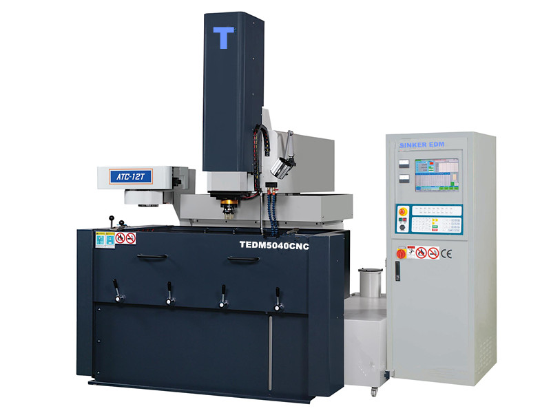
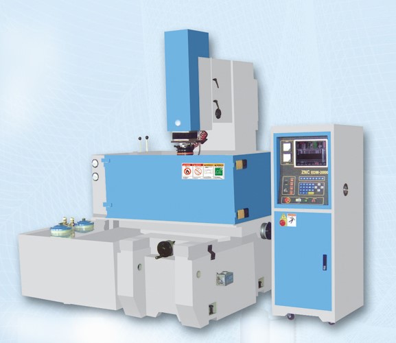
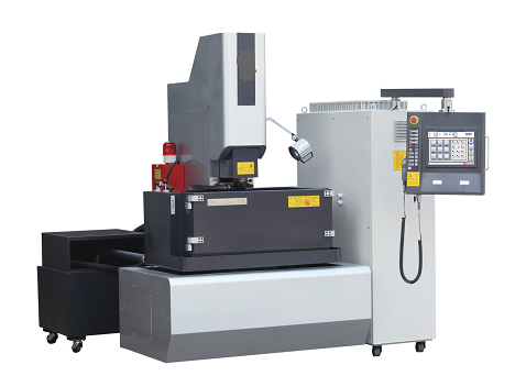
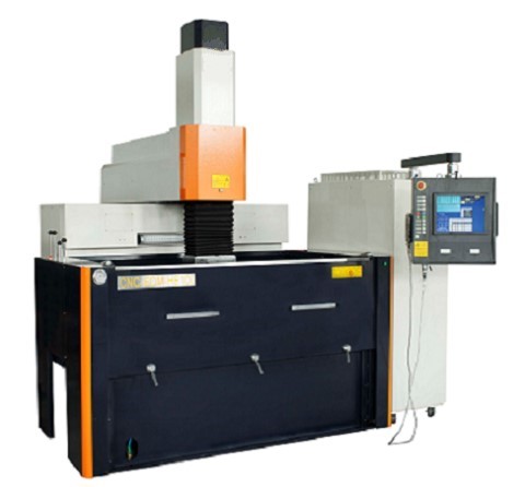
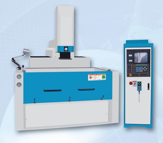
CNC Sinker EDM

Machine Features
I. Specification
|
Model |
TEDM5040CNC |
TEDM6045 CNC |
TEDM7050 CNC |
TEDM8060CNC |
TEDM1060CNC |
TEDM1270CNC |
|
X axis travel(mm) |
500(20") |
600(24") |
700(28") |
800(31") |
1000(39") |
1200(47") |
|
Y axis travel(mm) |
400(16") |
450(18") |
500(20") |
600(24") |
600(24") |
700(28") |
|
Z axis travel(mm) |
350(14") |
400(16") |
400(16") |
500(20") |
500(20") |
500(20") |
|
Work table(mm) |
900x500 (35"×20") |
900x500 (35"x20") |
1000x600 (39"×24") |
1200x700 (47"×28") |
1250x750 (49"×30") |
1400x850 (55"×33") |
|
Max work piece(mm) |
1300x870x520 (51"×34"×20") |
1500x970x520 (59"×38"×20") |
1700x1100x600 (67"×43"×24") |
1800x1150x600 (71"×45"×24") |
2000x1150x625 (79"×45"×25") |
2240x1300x625 (88"×51"×25") |
|
Max work piece weight(KG) |
2500 |
3000 |
3000 |
4000 |
4500 |
5000 |
|
Max electrode weight(KG) |
200 |
250 |
350 |
350 |
350 |
400 |
|
Machine net weight(KG) |
3520 |
3900 |
4800 |
5100 |
5700 |
6600 |
|
Oil level (mm) |
110~450 (4"~18") |
110~450 (4"~18") |
110~450 (4"~18") |
110~450 (4"~18") |
110~450 (4"~18") |
110~450 (4"~18") |
|
Occupy area LxWxH(mm) |
2870x3750x2670 (113"×148"×105") |
3100x3780x2670 (122"×149"×105") |
3570x3920x2780 (141"×154"×109") |
3930x3980x2880 (155"×157"×113") |
4010x4050x2880 (158"×159"×113") |
4380x4330x2920 (172"×170"×115") |
|
Table to electrode plate distance (mm) |
400~750 (16"~30") |
400~800 (16"~32") |
490~890 (19"~35") |
430~930 (17"~37") |
430~930 (17"~37") |
510~1010 (20"~40") |
|
Filter unit |
2 |
2 |
2 |
2 |
2 |
2 |
|
Filter barrel |
4 |
4 |
4 |
4 |
4 |
4 |
|
Oil capacity (L) |
780 |
1000 |
1500 |
1650 |
1900 |
2350 |
II. Windows CE controller
1. A dialog window with picture description.2. Special repaired frames to quicken the maintenance speed.
3. Close-loop design of digital feedback on three axes of the machine significantly increases positioning precision and ORBIT-CUT machining accuracy and efficiency.
4. Simple operation interface.
5. Common function keys are located on the operational panel for direct use.
6. Hot key setting.
7. ATC (automatic tool change) and C-axis 360° index can be installed; the process of coarse machining to ultra-fine machining can be completed at one time.
8. Dialogue diagram provides various hole-expanding modes such as quick search of edge, centers and datum marks.
9. Rich color graphic (the same resolution as a PC screen).
10. Automatic multi-step machining (coarse, medium coarse, medium fine, fine, superfine)—up to 10 steps.
11. Unlimited number of machining conditions can be saved as machining archives. Each set of machining conditions can be edited, modified or stored. They are easy to edit and easy to find.
12. Automatic origin search and multi-point coordinate memory capability.
13. 1/2 design capability, ARC automatic discharge waveform detection and automatic adjustment.
14. Automatic center position detection, automatic compensation, search of hole center and deepest point; fixed hole machining (cyclic mode, independent mode), which is suitable for different machining conditions; Radial, circular, square, linear (vector), coning, 45° hole-expanding machining.
15. Three-axis beeline, two-axis arc, three-axis helix.
16. Chinese/English versions interface, metric/British system switch and Z-axis quick up, quick down, slow up and slow down capability.
17. Lateral machining, three axes, six directions (plane rotation).18. All alarms describe the source, date and exact time of problem occurrence.
20. Optical scale is applied for close-loop position control, enabling extreme position for machining.
21. Automatic editing—settings can be done according to type of material, work piece size, machining depth, one side die clearance, final current and rate of electrode wear.22. CNC models possess conventional capability of consistent level of energy discharge, achieving stable and rapid machining and smooth high quality on machining surface while the rate of electrode wear is still low.
23. Monitor page indicates machining path and orbital pattern in use.
III. Controler Type
| power supply |
Unit
|
E30
|
E50
|
E75
|
E100
|
E150
|
E200
|
| Max.Machining current |
|
30A
|
50A
|
75A
|
100A
|
150A
|
200A
|
| Meral removal rate |
(mm3/min)
|
250
|
400
|
600
|
850
|
1250
|
1600
|
| Power input |
|
3KVA
|
4.5KVA
|
6.5KVA
|
8KVA
|
16KVA
|
22KVA
|
| Min.Electrode ware |
|
0.20%
|
0.20%
|
0.20%
|
0.40%
|
0.60%
|
0.70%
|
| Best surface finishing |
|
0.2
|
0.2
|
0.3
|
0.5
|
0.7
|
0.7
|
| N.W. |
kgs
|
200
|
200
|
300
|
330
|
450
|
480
|
| packing size (LxWxH) |
mm
|
620x740x1820
|
620x740x1820
|
620x740x1820
|
620x890x2000
|
620x1140x2000
|
620x1140x2000
|

- Home - About us - New products - News - FAQ - Inquiry - Contact us - Sitemap